Building Energy Performance Ontology
1. Introduction
The conceptual design of Civil Engineering systems is a highly complex process that involves a series of decisions that reflect to the whole life cycle of the system – from construction to the operational and demolition phases (Frangopol and Liu 2007). The first step of the conceptual design phase is to create a list of requirements that the principle solution should meet (Pahl et al. 2007). To set the requirements list, it is essential that architects, engineers, clients, contractors, and everyone involved in the project, be engaged to identify client needs, system specifications, potential costs, and implications of the project. To adduce an example, conceptualizing a building can be completely different for architects focusing on circulation space, energy modelers trying to improve building performance, or fire safety specialists that need to meet fire protection requirements. Inevitably, the cooperation of different parties requires the use of a common vocabulary that facilitates information sharing between the different domains of knowledge. This common machine-interpretable vocabulary is offered by ontological developments and basically consists of classes (main concepts), properties (key characteristics that define the classes), and instances (individual instances of classes)(Noy and Mcguinness 2001). More specifically, (Gruber 1993) defined ontology as an “explicit specification of a conceptualization” that can be shared and re-used by other people or software agents. To illustrate the process of developing an ontology, this report decomposes the domain of building energy performance simulation (BEPS), as an essential engineering system during the conceptual design of buildings. Considering that ontologies are made for re-use, the primary aim of this work is to share the required knowledge to create a valid building energy model.
2. Building Energy Performance Simulation (BEPS) domain
Considering that buildings consume more than 40% of global energy (IEA 2013), creating a valid energy model that is able to simulate the “real” performance of the building is crucial for making optimal decisions during the conceptual design phase; however, creating a model to represent reality is still a considerable challenge. According to (Box and Draper 1987), “Essentially, all models are wrong, but some are useful” or in other words, all models are based on assumptions and uncertain inputs that augment the gap with reality, yet a well-structured model still provides valuable predictions. To ensure that the proposed ontology fully represents the knowledge of a valid energy model, we decompose the BEPS domain using the accredited – by (ASHRAE 2019) – validation process of BES software. This method is known as BESTEST (Building Energy Simulation TEST) and explains the main functions and components of a model, while describes the inputs required to create a valid building energy model in detail (Judkoff and Neymark 1995).
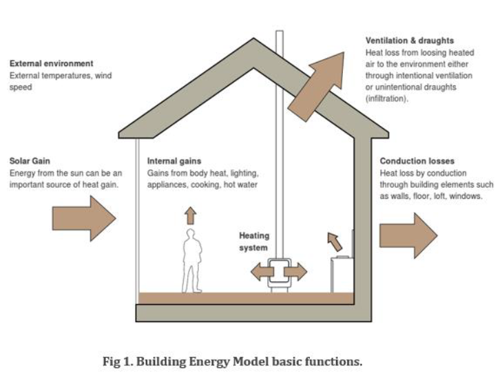
To explain graphically the main functions of a building energy model, Fig 1 represents a building as a thermal model on which energy is transferred as a result of indoor vs outdoor temperature variations. Heat is transferred (gains or losses) through the building components (walls, roof, windows, etc.) while direct gains of heat usually stem from solar and internal gains (cooking, occupants, lighting, equipment, etc.). Furthermore, ventilation and infiltration result in heat gain/losses as well as in changes of airflow affecting the indoor air quality (i.e. level of CO2 concentration). In addition, the role of HVAC systems is to retain the internal temperature and humidity at a certain level, by adding or extracting heat from the space. Finally, a building energy model is strongly dependent on location and climate details (e.g. affecting solar gains) and requires a set of simulation parameters in order to perform a dynamic simulation (e.g. timestep – frequency of static simulation).
The proposed ontology aims to classify the information required to create a valid building energy performance model and can be useful to create parametric building energy models in terms of exploring the different parameters influencing energy performance.
3. BEPS Ontology development
In the first steps towards developing the proposed ontology, we define the purpose, the scope, the design intent as well as the potential reuse, following the development processes as described by (Noy and Mcguinness 2001). The following definitions help us understand what kind of information an energy modeler requires to create a valid energy model, who is expected to make use of this ontology, and how it is designed for reuse.
- Purpose: This ontology represents concepts needed to create a proper thermal model for building energy simulation. It aims to offer a tool for building energy modelers (non-experts) to understand the requirements for simulating building energy performance.
- Scope: This ontology includes concepts such as building physical components, material properties, weather conditions, occupancy, schedules, and their relations.
- Intended end-users: The intended end-users are energy modelers as well as non-experts involved in the conceptual design of buildings.
- Intended use: The ontology aims to represent knowledge to support parametric energy modeling and include the requirements for the successful creation of a thermal model. Using this ontology, the users will be able to better understand the requirements of a building energy model and the concepts that affect its predictions.
- Re-use: The ontology is developed to support the development or combination with other ontologies in the domains of HVAC systems, Building Automation Systems (BAS), Building Energy Management Systems (BEMS), and Daylighting Analysis. Combing the proposed ontologies with the aforementioned could create useful insights in the conceptual design of buildings as well as in their maintenance.
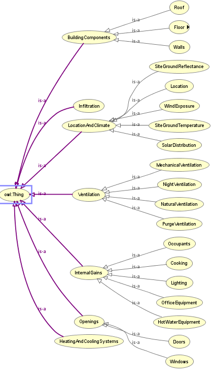
In the next steps, the classes of the ontology are defined using a “top-down” development process. In this approach, the most general concepts “Location and Climate”, “Building Components”, “Ventilation”, “Infiltration”, “Openings”, “Internal Gains”, “Heating and Cooling Systems” are designed as the main classes and are further analyzed with subclasses. For example, “Building Components” is defined as a subclass of “Construction” and subsequently, “walls”, “floors” are defined as subclasses of “Building Components”. In other words, “Building Components” is considered a superclass of the classes “walls”, “floors”, etc. (Noy and Mcguinness 2001). To include further information in our ontology, properties of classes are defined such as “materials” and sub-properties such as “U-value”, “Thickness” etc. The final ontological development steps include the definition of relationships between classes and properties. In this process, we are able to define the key characteristics of properties and sub-properties; for example, whether a property is transitive, the inverse has a domain or range to incorporate the formal description logics (Krötzsch, Simancik, and Horrocks 2013).
More details on the ontological development specifications are provided within the provided ontology web language (“BEPS.owl”) file. To identify how the ontological model will infer the relationships between the defined concepts, the reasoning engine “Pellet” is used in Protégé. Finally, to gain a sounder understanding of the conceptual specification of BEPS ontology, a graph is produced by the aid of the “Ontograph” tool in Protégé and is illustrated in the following figure.
REFERENCES
ASHRAE. 2019. “Standard 90.1.” https://www.ashrae.org/technical-resources/bookstore/standard-90-1.
Box, George E. P., and Norman R. Draper. 1987. Empirical Model-Building and Response Surfaces. Empirical Model-Building and Response Surfaces. Oxford, England: John Wiley & Sons.
Frangopol, Dan M., and Min Liu. 2007. “Maintenance and Management of Civil Infrastructure Based on Condition, Safety, Optimization, and Life-Cycle Cost∗.” Structure and Infrastructure Engineering 3 (1): 29–41. https://doi.org/10.1080/15732470500253164.
Gruber, T. 1993. “KSL 92-71 Revised April 1993 A Translation Approach to Portable Ontology Specifications By.” 1993. /paper/KSL-92-71-Revised-April-1993-A-Translation-Approach-Gruber/d41f4b30a90063ac73d6a2224d338d5df493a6fc.
IEA. 2013. “Policy Pathway – Modernising Building Energy Codes 2013 – Analysis.” https://www.iea.org/reports/policy-pathway-modernising-building-energy-codes-2013.
Judkoff, R., and J. Neymark. 1995. “International Energy Agency Building Energy Simulation Test (BESTEST) and Diagnostic Method.” NREL/TP–472-6231. National Renewable Energy Lab. http://inis.iaea.org/Search/search.aspx?orig_q=RN:33052752.
Krötzsch, Markus, Frantisek Simancik, and Ian Horrocks. 2013. “A Description Logic Primer.” ArXiv:1201.4089 [Cs], June. http://arxiv.org/abs/1201.4089.
Noy, N., and Deborah Mcguinness. 2001. “Ontology Development 101: A Guide to Creating Your First Ontology.” Knowledge Systems Laboratory 32 (January).
Pahl, Gerhard, Wolfgang Beitz, Joerg Feldhusen, and Karl-Heinrich Grote. 2007. “Chapter 6: Conceptual Design.” In Engineering Design: A Systematic Approach. https://doi.org/10.1007/978-1-84628-319-2.
BEPS Parametric Model (Atrium design)
1. Introduction
The first step for the design of a civil engineering product is to conceptualize a principal solution that meets a list of requirements based on multiple parameters and certain performance criteria such as efficiency, costs, and performance (Pahl et al. 2007). To address the complexity of the principal solution, it is required to define the most pivotal parameters that influence the key performance criteria to provide a better civil engineering product. In the last decades, 3D parametric modeling (Sacks, Eastman, and Lee 2004) is used to support design decisions by the aid of Computer-Aided Design (CAD) systems while more recently, object-based modeling approaches, such as Building Information Modelling (BIM) (Eastman et al. 2011) have revolutionized the project design process and paved the way for the use of optimization and artificial intelligence (Shea, Aish, and Gourtovaia 2005) for the generation of optimal civil engineering products.
Nevertheless, optimization often neglects the geometrical rearrangement of components (Geyer 2008). In this work, parametric modeling is applied to investigate different geometrical design configurations of a building with respect to its energy and daylight performance. For this investigation, the widely adopted BIM authoring tool “Revit” is supported by the visual programming environment “Dynamo” which integrates automation in the BIM process. Aiming to understand the application of the method in the building performance domain, the geometric embodiment of the building will remain as simple as possible, drawing valuable conclusions for the benefits and limitations of the method in producing environmentally effective design solutions.
2. The design challenge
In every parametric modeling project, it is essential to identify the key performance criteria which will drive the design process. One of the most well-known “design trade-offs” in the building performance domain is to minimize energy consumption and maximize daylight access while a high level of comfort (thermal and visual) is maintained for the users. More precisely, in cold climates (such as Berlin), the designer aims to maximize the solar gains by maximizing the access to direct solar radiation; however, direct solar radiation can
lead to extreme visual access (~1000lux) which leads to discomfort while a typical visual comfort standard requires to retain internal condition around 200-300 lux. On the other hand, less access to daylight can increase energy consumption for heating the space and artificial lighting. In fact, the designer seeks to find the optimal daylight distribution within the space while keeping energy consumption low. Overall, the performance criteria are listed below and are provided by energy simulation software packages (such as EnergyPlus): Energy consumption (kWh), Daylight Access (lux), Thermal Comfort (Hours of discomfort).
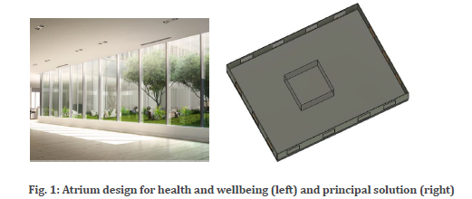
To address the aforementioned design challenge, an “atrium” is selected as a design approach that increases the access to natural daylight, blocks direct solar access which can be problematic (Fig.1), and increases health and wellbeing in the space. In practice, this decision is made in the very early design stage by the architects, usually based on aesthetics and space circulation criteria, without testing how the design of the atrium (size, location, etc.) will affect the building performance. Hence, it is important to develop a parametric model of the principal solution provided in Fig.1.
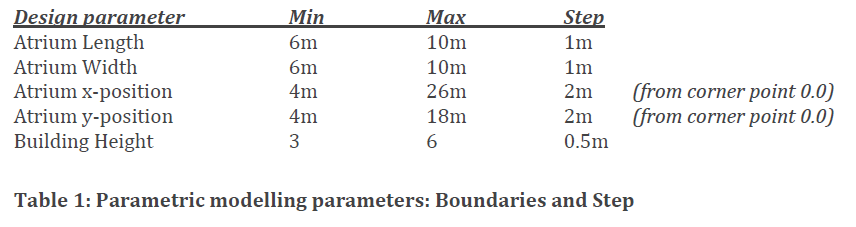
The goal of the proposed parametric model is to provide the design team (both energy modelers and architects) with automated configurations of the model so that they can explore their feasibility in more detail. The following five parameters are selected as the most important ones that influence the performance of the atrium:
▪ Atrium Length (1) and Width (2): Obviously, the larger the area of the atrium, the better performance is achieved – but there are architectural constraints in terms of indoor space availability.
▪ Atrium position y-axis (3) and x-axis (4): The position of the atrium is strongly related with the sun movement. Offering a variety of atrium positions can help the energy modeler identify the best possible position (south/north etc.). Of course, other parameters such as space use will influence the selection from the designers.
▪ Building height (5): A taller building can block the direct solar gains (Fig 1), influencing the performance of the “atrium”. However, more space might lead to
higher energy demand for heating and cooling the space as well as higher construction costs.
It is important to mention that parameters 1&2 are confined by parameters 3&4 since a larger atrium is not positioned in the same way as a shorter atrium. This feature increased the complexity of the parametric model in Dynamo. In practice, the proposed parametric model generates configurations with the atrium in the corners of the buildings. This would not be a wise design solution but represents the boundary condition in the model. The minimum and maximum size of the atrium is 36m2 and 100m2 respectively and are meant to meet any possible design requirements. More details on the modeling approach are provided in the Dynamo and Revit files.
3. Analysis and Results
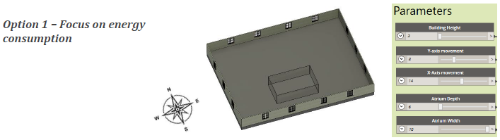
In this section, three example configurations are presented in order to support the engineering design with further directions on how to select the best model. Three options are provided with each one focusing on a different key performance criterion.
Option 1 is expected to provide the best possible results on the energy consumption. Considering the location of the building in the northern hemisphere and within the cold climate of Berlin, the atrium has been designed with the maximum exposure to solar gains. The minimum building height will provide maximum direct solar radiation that will decrease the heating needs in winter. However, issues may arise in terms of visual comfort as well as thermal comfort due to overheating during Summer. Further investigation is required by energy simulation experts.
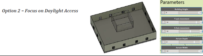
In option 2, the highest ceiling is selected to block the direct solar gains in the building. Furthermore, the atrium is located in the northern part of the building which is expected not to have access on direct solar radiation, offering better distribution in the daylight access. However, increasing the height of the building means more construction costs as well as operational costs due to increased needs of energy for heating in winter. In contrary, better performance is expected in summer where passive ventilation system can be applied (e.g. stack effect).
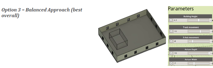
Finally, option 3 offers a more balanced design approach and could be a possible optimal solution for the building. The atrium is located on the western part where the sun
power is less intense and have some access on the southern part for more solar gains. Building height is on an average value to block the direct solar radiation only in the front of the atrium (south part). Furthermore, the atrium is expected to be a place where out-of-work activities take place (later in the day), following the sun path.
4. Conclusion
Parametric modelling can become highly complex when it incorporates geometrical configuration; yet, the results show how it can be applied effectively through Dynamo and Revit to inform the principal model of a building. The current approach can be further enhanced taking into consideration the glazing ratio of the atrium as well as the window-to-wall ratio and shading components. Overall, to make use of the large number of configurations, generative optimization algorithms can be applied to identify the optimal solutions according to the performance criteria. A pareto font can also be used to visualize the optimal solutions.
REFERENCES
Eastman, Charles M., Chuck Eastman, Paul Teicholz, Rafael Sacks, and Kathleen Liston. 2011. BIM Handbook: A Guide to Building Information Modeling for Owners, Managers, Designers, Engineers and Contractors. John Wiley & Sons.
Geyer, P. 2008. “Multidisciplinary Grammars Supporting Design Optimization of Buildings.” https://doi.org/10.1007/S00163-007-0038-6.
Pahl, Gerhard, Wolfgang Beitz, Joerg Feldhusen, and Karl-Heinrich Grote. 2007. “Chapter 6: Conceptual Design.” In Engineering Design: A Systematic Approach. https://doi.org/10.1007/978-1-84628-319-2.
Sacks, Rafael, Charles M. Eastman, and Ghang Lee. 2004. “Parametric 3D Modeling in Building Construction with Examples from Precast Concrete.” Automation in Construction 13 (3): 291–312. https://doi.org/10.1016/S0926-5805(03)00043-8.
Shea, Kristina, Robert Aish, and Marina Gourtovaia. 2005. “Towards Integrated Performance-Driven Generative Design Tools.” Automation in Construction, Education and Research in Computer Aided Architectural Design in Europe (eCAADe 2003), Digital Design, 14 (2): 253–64. https://doi.org/10.1016/j.autcon.2004.07.002.