Introduction:
In general, retaining walls are used for keeping soil, rock, hardscaping and landscaping in its place. To avoid any overturning or sliding especially in uneven elevations. Soil cemented retaining wall is, however, used during excavation as a temporary construction for support. It is used as it provides provides long term uplift resistance in places of depression or elevation along long passages. [1]
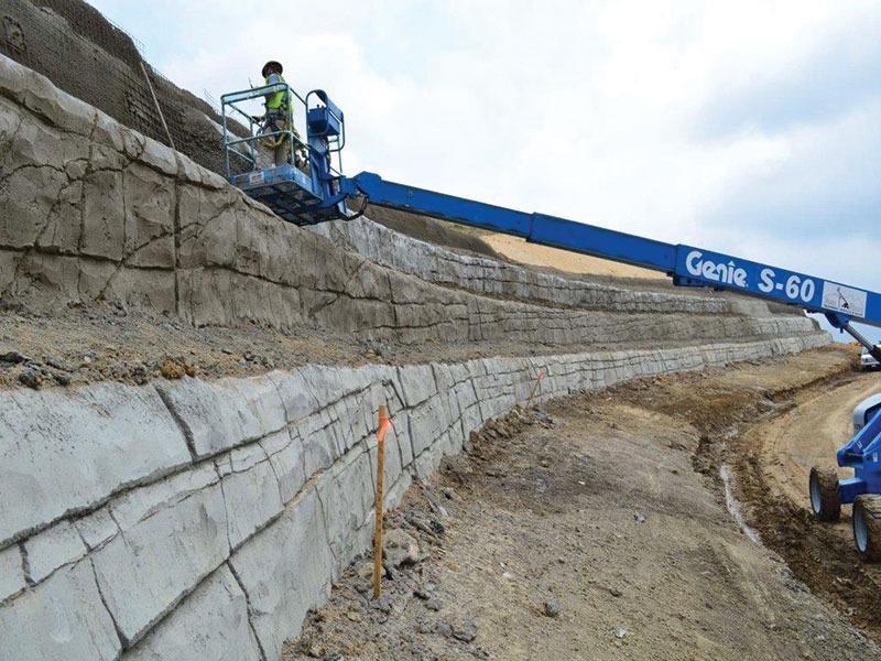
Fig 1 : A soil cemented retaining wall
In mega infrastructure projects, which involve pavements and pipelines in mountainous regions, soil cemented retaining walls can be a good solution to avoid any landslide or avalanche that could cause damage to the property.
Boundary Conditions:
When considering the environmental effects of a specific civil system, particularly in terms of gas emissions, it is crucial to evaluate its life cycle stages and determine the sources of emissions at each stage. These emissions are associated with the energy consumed during the extraction and manufacturing processes, as well as the emissions released during material transportation. Environmental effects and gas emissions associated with a specific civil system’s life cycle can vary greatly depending on its design, construction methods, energy sources, operational efficiency, and maintenance practices. [2]
Conducting a life cycle analysis specific to the civil system requires setting boundaries to ensure the consistency and comparability of assessments (Figure 1).
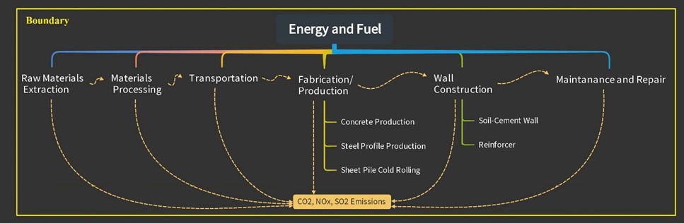
Figure 1: Boundary for LCA analysis of Soil-Cemented Wall
There are various types of Soil-Cemented walls but three options were chosen from previous case studies [3]. These walls are constructed in various ground profiles and lengths while having different support systems but they approximately have supported the same height. More details about these design options are presented in (Table 1&2).
| Options | Wall Type | Wall DescriptionW × D ×L (m) | ReinforcementSupport Type | Supports Description | System surface |
| Option 1 | Soil-Cement Wall “TYPE1” | 0.6 × 4.5 × 40 | H.Pile | W16 × 40 | Wall |
| Option 2 | Soil-Cement Wall “TYPE2” | 0.9 × 4.5 × 50 | Sheet.Pile | XZ85 × 50 | Steel |
| Option 3 | Soil-Cement Wall “TYPE3” | 2.6 × 4 × 60(Triangular cross-section) | Nail.Bar | #9 | Shotcrete |
Table 1: Description of design options for the study
| Element | kg/m or thickness (m) | Material |
| H.Pile , W16 × 40 | 59.8 kg/m | ST37 |
| Sheet.Pile , XZ85 × 50 | 109 kg/m2 | ST37 |
| Nail.Bar, #9 | 5.06 kg/m | ST37 |
| Shotcrete | 0.07 m | Mortar (25) |
Table 2: Life Cycle Inventory of different materials in the study
Maintenance Planning:
The lifespan of a retaining wall can be prolonged for 100 years under the right planning to maintain it. There are several types of repair and maintenance that can be implemented to prevent or correct the state. Grading, treating minor cracks, steel profile replacement, sheet pile-coating, sheet pile re-welding, sheet pile replacement and nail bar replacement are some of the practices which are being considered here.
Setting interventions for maintenance before conducting a Life Cycle Assessment (LCA) analysis is crucial in understanding the overall environmental impact of a product, process, or service. LCA is a systematic approach that evaluates the environmental performance throughout the entire lifecycle. We should note that the maintenance of the system or the subsystems can excessively alter the results so a brief look into the interventions of the design options is shown below. [4]
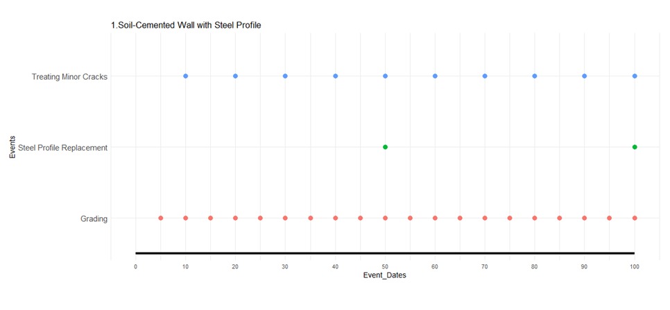
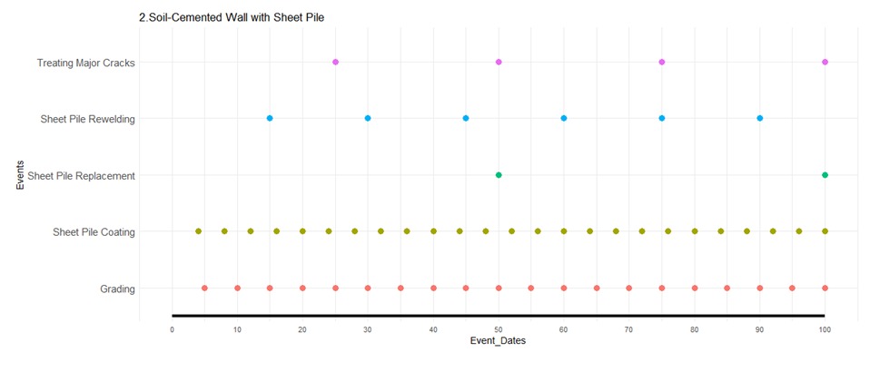
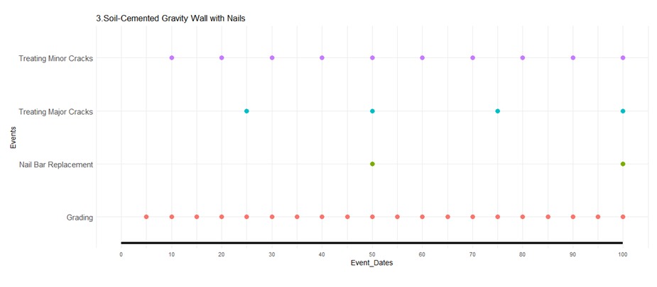 Fig 2 : Design Option 1 Fig 3 : Design Option 2 Fig 4 : Design Option 3
For the integration of this sub-system into the whole system. Some maintenance considerations were taken and span changed to 60 years. The timeline for the integration of retaining wall is presented in the figure below.
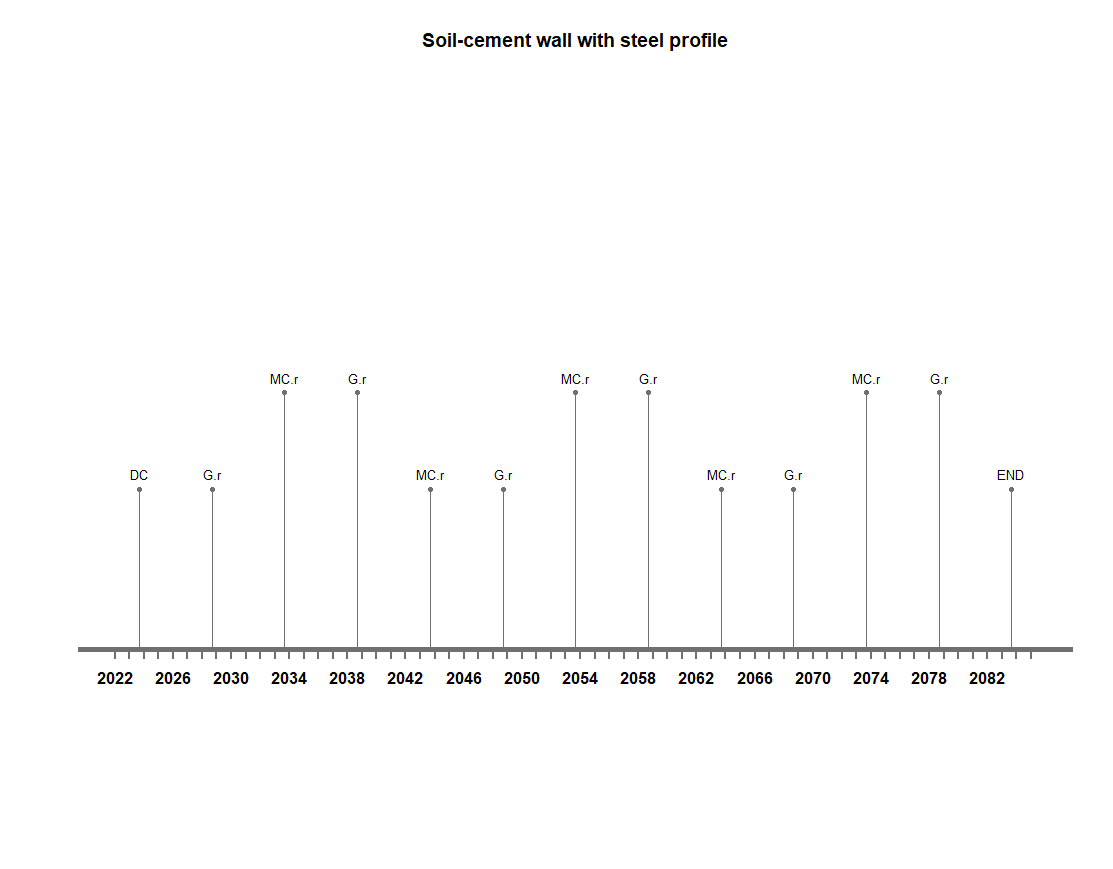
Fig 5 : Updated Timeline of Retaining Wall
Life Cycle Analysis:
This study is conducted via a code in R-Studio for the consumed energy and CO2, SO2, and NOx emissions for each three design options. On the basis of the energy consumption and emission for the designed boundary conditions highest carbon footprint is by design option 2.
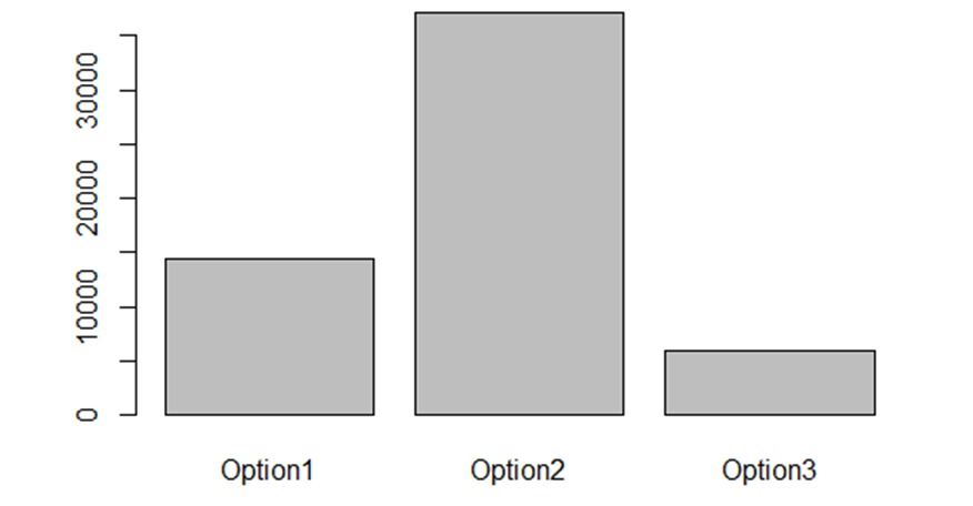
Fig 6 : Energy Consumption of different design option (MJ)
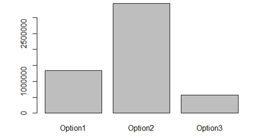
Figure 7: CO2 emission for different design options (kg)
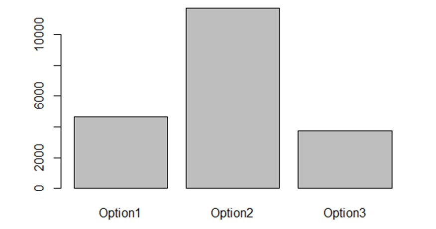
Figure 8: NOx emission for different design options (kg)
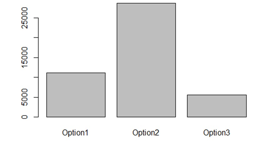
Figure 9: SO2 emission for different design options (kg)
Analytical Hierarchy Process:
Multiple Criteria Decision Making field is a type of AHP which involves breaking down the decision problem into smaller, more manageable components, and determining the relationships between these components.[5] This process was involved to get a better understanding. Our objective is to prioritize design options, taking into consideration criteria such as energy, CO2, NOX, and SO2.
Upon reviewing the bar plots depicting the levels for each indicator, we initially favored Option 3 (Soil-Cemented wall with Nail Bars) due to its exceptionally low level across all indicators. However, upon examining the Pie chart, a more comprehensive evaluation of our preferences has resulted in a shift in ranking. According to the AHP method results, Option 2 (Soil-Cemented Wall with Sheet Piles) emerges as the top choice, boasting the highest score. (Figure 10)
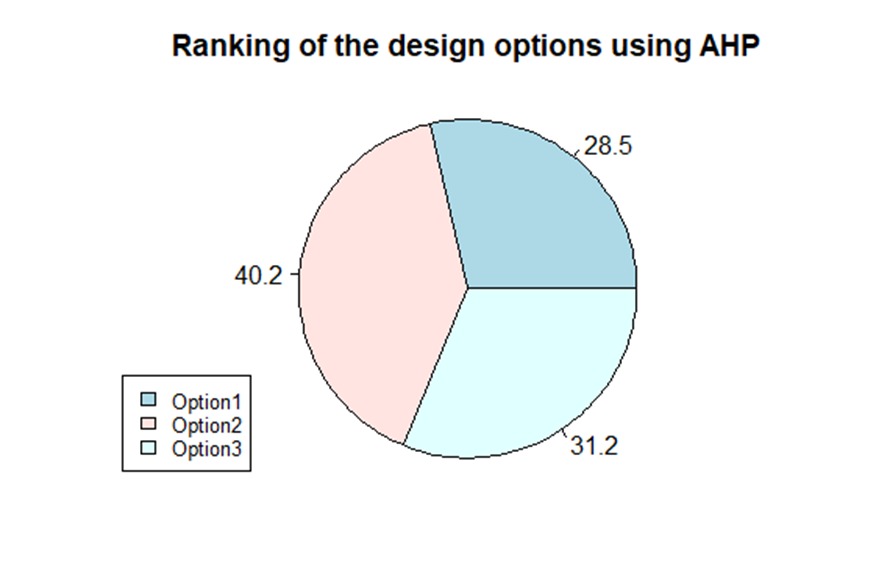
Figure 10: Score for the three options after AHP analysis
References
[1] Soil Cemented Walls for Excavation Support by David S, Yang, Raito, Inc