Abstract
In this assignment, I create a series of analyses based on the tutorial document. A set of timelines are created, showing how different kinds of interventions are arranged in time sequence. An emission assessment model established presents energy cost and other environmental indicators, like CO2, SO2 and phosphate, concerning different choices and combinations of genres of column and repair techniques.
1. Introduction
The strengthening of concrete structure is a hot field with the undergoing of building structure ageing and climate change. On the one hand, construction and demolition waste might have accounted for up to. On the other hand, the portion of the ageing building is relatively higher and still increasing in the developed region. By 2005, residential buildings in Europe and private buildings in Hong Kong more than 30 years old accounted for about 70% and 33.33%[1], respectively. Therefore, techniques and schedules need to be prepared to tackle the consequence of this historical problem[2]. Many strengthen techniques have been developed. The most common and economic one is plate bonding, with different materials like steel plate, in general, or FRP, as known as fiber-reinforced
polymers, which is considered as a promising new material in civil engineering. Although there are limitations of these techniques. For instance, researches show that FRP confinement performs less effective in the reinforcement of square columns. The sharp corners weaken the performance of the system. There are also techniques without warping, although, they need to intrude the structure. The planting-bar reinforcement drills RC component and plants new rebars in the drilling holes, with reinforcement glue. However, it’s not typically for building reinforcement in the first place. It was originally developed to reinforce the tunnel and mines from the 1960s. What’s more, the requirements in the construction site are also strict. The surface of the bar with rebar-planting should be clean without besmirching and drying and the glue, also called anchor adhesives, must be compacting without a cavity.
2. Model development
2.1 Goal and scope of the assessment
The main goal is to do a carbon footprint analysis, and the boundary and scope of this assessment are shown on Figure 1.
2.2 Column structure
The structure of the column are squares cross-section RC column and H-cross-section steel column, omitting the structure of joints. To determine a specific scale, we can assume the column is in a normal section axial compression state.
Assuming the column bears an axial force of N = 1500 kN, with a ratio of reinforcement ρ=2%. The axial compressive strength of the concrete is 𝑓𝑐=16.7 𝑁/𝑚𝑚2 . We can also choose axial rebar as HRB400 in the specification of TB 10092-2017, where the compressive strength is 𝑓𝑦=360 𝑁/𝑚𝑚2 , as well as the extension strength.
The cross area would be
𝐴=𝑁0.9(𝑓𝑐+ρ 𝑓𝑦)= 15000000.9×(16.7+0.02×360)=82102 𝑚𝑚2 (1)
2.3 Materials
The materials in this assessment are Q420 steel and C35 concrete including its components. The materials made for concrete can be computed with the method of mix proportion. To make this part succinct, I directly use an excel calculator made by myself during sophomore, which will be uploaded as an accessory. I choose gravels as coarse aggregates. The results and the rest of the parameters are shown in the Figure 3.
The ratio is, 𝑚𝑐𝑒𝑚𝑒𝑛𝑡:𝑚𝑓𝑙𝑦 𝑎𝑠ℎ:𝑚𝑤𝑎𝑡𝑒𝑟:𝑚𝑓𝑖𝑛𝑒 𝑎𝑔𝑔𝑟𝑒𝑔𝑎𝑡𝑒𝑠:
𝑚𝑐𝑜𝑎𝑟𝑒𝑠 𝑎𝑔𝑔𝑟𝑒𝑔𝑎𝑡𝑒𝑠=1:0.01:0.45:1.48:2.41 (11)
Based on that, the material sheet can be computed with energy and other matters emissions. The sheet is in Chart 3. Now we have three options for columns and four emission indicators.
2.4 Repair
There are four repair measures to introduce. The first one is RC jacketing. After cleaning and roughening the surface, several steel strips will be inserted to help locate rebars; Then a new rebar frame will be built with a larger cross-section; Adhesive will be spread on the surface; New concrete cast in. Figure 4 shows the general process[3].
The second one is similar to the former, with a different material, steel. Moreover, the construction technique also has a slight difference. The surface of concrete needs to be peeled off before steel straps deploy. Figure 5 presents the general process The third technique is FRP confinement[4]. It is usually conducted by providing fiber reinforced polymer (FRP) around reinforced concrete columns. This strengthening technique is specifically influential when the column is circular.
However, if the reinforced concrete column is rectangular and the ratio of depth to width of a column is larger than 2 or the smallest side of the column is greater than 900mm, then ACI 440.2R-08 is not applied for this strengthening method. Figure 5 shows the effective area of the confinement.
3. Life Cycle Timeline
3.1 model in R
The structure of the codes is pretty much like the one in the tutorial. I didn’t find one solid source of data that tracked every building’s maintenance and repair. There are just independent repair and renewal records, like Portland building exterior envelop and structural improvement.[8] Therefore, I will assume that buildings have regular maintenance every 5 years. For RC structure, the repair time interval would be 15 years and replacement for 25 years. For PRC structure, with more brittle joints, the repair time interval would be 10 years and replacement for 45 years. For the steel column, the repair time interval is 15 years and the replacement for 20 years. Therefore, the parameters for M, R and DR(CR) are settled.
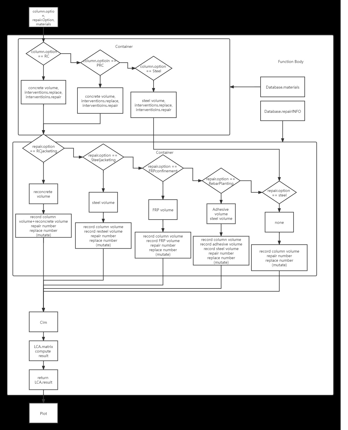
Figure 10 Flow chart of emission computation
4.2 Results
The correspondences between choices and options are given in the Chart 4. The steel consume the highest level of energy while it does not emit in proportion. Part of reason it’s because the amount of usage is the lowest among all candidates. RC and PRC produce the most CO2, considered in these results. Due to attributes itself, The concrete and steel perform similarly in SO2 indicator despite their differences in usage
Reference
[1] Aashish Sharma, Abhishek Saxena, Muneesh Sethi, Venu Shree, Varun, Life cycle assessment of buildings: A review, Renewable and Sustainable Energy Reviews, Volume15, Issue 1, 2011, Pages 871-875, ISSN 1364-0321,https://doi.org/10.1016/j.rser.2010.09.008. (https://www.sciencedirect.com/science/article/pii/S1364032110002959)
[2] Protection of Historical Constructions, Proceedings of PROHITECH 2021, Ioannis VayasFederico M. Mazzolani.
[3] The Constructor Website Methods of Strengthening Concrete Columns – The Constructor
[4] The Constructor Website Design of FRP Axial Strengthening of RCC Columns -ACI 440.2R-08 – The Constructor
[5] Lv, Nan, and Hui Min Li. “The Research of Several Problems That Merit Attention in Use of Rebar-Planting Anchorage Technique for Reforming and Strengthening Buildings.” Applied Mechanics and Materials, vol. 351–352, Trans Tech Publications, Ltd., Aug. 2013, pp. 1333–1336. Crossref, doi:10.4028/www.scientific.net/amm.351-352.1333.
[6] The Constructor Website How to Replace Damaged Concrete Members in Structures? – The Constructor
[7] Database of ÖKOBAUDAT Search | Database | ÖKOBAUDAT (oekobaudat.de)
[8] The Portland Building Repair Timelinee The Portland Building – Previous Study and Repair Timeline (portlandoregon.gov)
[9] An extension of TOPSIS for group decision making, April 2007Mathematical and Computer Modelling 45(7-8):801-813, DOI: 10.1016/j.mcm.2006.03.023, SourceDBLP
[10]Forecasting Repair Schedule for Building Components Based on Case-Based Reasoning and Fuzzy-AHP, Sojin Park, Nahyun Kwon * and Yonghan Ahn *, Sustainability 2019, 11, 7181; doi:10.3390/su11247181