Explanation of System:
A dam represents a barrier across a river to control the flowing water. They are designed for different benefits such as irrigation of water for agriculture, control of floods, electrical generation, navigation, or water storage. Dam structures will play an important role in the exploitation of hydropower generation and water management. [1]

For system integration of our subsystems, we have chosen the Hydropower Dam type. This dam uses the energy of the falling water to generate electricity. The water held high is fed through sluices into turbines, which drive a generator to produce electricity.
The largest component of the dam is its barrier structure, which must withstand the load effects of water pressure. This is where the largest quantities of material are consumed. Therefore, it is particularly interesting to study this subsystem for the life cycle analysis of this structure.
Barrier structure
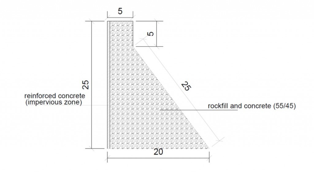
The rock-fill concrete dam is a newer approach to the design of a dam body, using large stones in combination with lower cement content. (Figure 3) The ratio is 55% rock-fill and 45% concrete. The structure has a reinforced concrete layer on the waterside (1,5 mass per cent steel). The cross-sectional dimensions were designed using comparative objects. [2]

Maintenance:
Large dams are designed for a lifetime of 100 years. The barrier structure as the main element of the dam is therefore designed for the entire life of the structure. However, some existing structures have already exceeded this period. In general, the construction of large dams is not expected to require the replacement of major components of the supporting structure. [3] For the dam, no maintenance measures are planned in advance to replace specific structural elements. However, based on system deterioration assumptions, it is possible to estimate the extent to which maintenance measures will be required after a certain period of time. The in-depth safety inspections of dams are carried out every 15 years, followed by a partial renewal (PN) of the water-side impermeable concrete layer. These are the main inspections. Every 6 years, normal less elaborate maintenance measures are scheduled. Therefore, I assume the implementation of minor repairs (MR) (e.g. crack injection). A complete repair of the water-side layer is necessary after 60 years (CR). [4]
The maintenance concept for the rock-fill concrete dam barrier structure is as follows:
RFC: MR= 6 years, PN = 18 years, CR = 60 years
The resulting maintenance planning timeline looks as follows:

Embodied Energy and Emissions:
By determining the quantities and offsetting them against the associated emission values per material quantity, the emissions for the LCA phases of material extraction up to the erection of the structure on the construction site are calculated. The result of this calculation results in the following values for the Dam barrier structure. The length of the dam is 100 m. The remaining values correspond to the cross-section. [5]
Material values for 100 m width and 25 m high rock fill concrete dam barrier structure:
- 13.500 t of concrete
- 12,5 t of steel
- 14.347,5 t of rock
Emissions for 100 m width and 25 m high rock fill concrete dam barrier structure:
- 2395,85 t of CO2
- 550,83 t of NOx
- 3664,94 t of SO2
- 19.695.950 MJ
References:
[2] Jin, F.; Huang, D.: Rock-Filled Concrete Dam. Springer Nature Singapore, Singapore, 2022