[1] Dam – spillway discharge
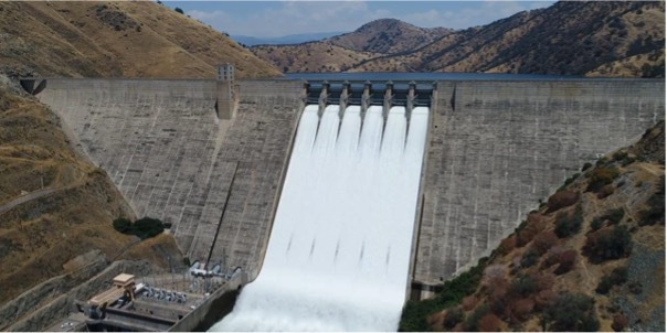
A dam is an engineered structure designed to control and store water, addressing modern needs like water supply, flood management, irrigation, and renewable energy generation. The reservoir equalizes the seasonal flow distribution and reduces its fluctuations. For dams, the expected service life goes from 50 to 100 years. [2]
A spillway is a structure designed to allow excess water to flow over or around a dam when the reservoir reaches its full capacity. Spillways are critical safety features for many types of dams. They can direct water over the dam, a specific section of it, through a channel around the dam, or via a conduit running through it. To protect the dam’s foundation, the energy of the water is dissipated at the base of the spillway, preventing erosion. [3]
Carbon analysis stages impact the environment through emissions and waste. Raw material extraction (e.g., limestone for cement) and processing are energy-intensive, emitting CO2, NOx, and SO2. [4] Production and construction involve machinery and material transport, generating further emissions. Maintenance and end-of-life stages add emissions from repairs, demolition, and recycling or disposal. Inputs include materials, diesel, and electricity, while outputs are emissions and waste. Comparing designs helps identify the most sustainable option to reduce environmental impact. The figure below shows the spillway life-cycle scope and boundaries.
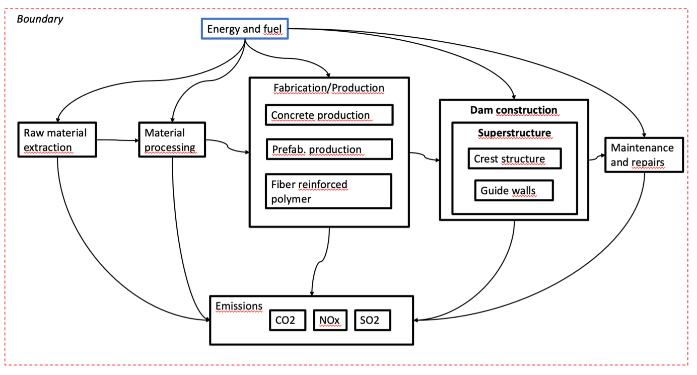
Scope and boundary for the system
Material selection is vital in civil system design, as different materials impact performance, cost, and environmental goals. The table below presents three design options, all primarily using concrete for the spillway. Concrete’s key advantages are its strength and durability, enabling it to withstand high water pressure and resist erosion.
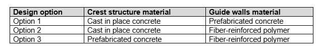
Spillway design options
After evaluating the maintenance timelines for each option and defining the Life Cycle Inventory, we established the goal and scope of our LCA. The selected environmental performance indicators for analysis are:
– Energy Consumption (MJ) (top left)
– CO2 Emissions (kg CO2 eq.) (top right)
– NOx Emissions (kg NOx eq.) (bottom left)
– SO2 Emissions (kg SO2 eq.) (bottom right)
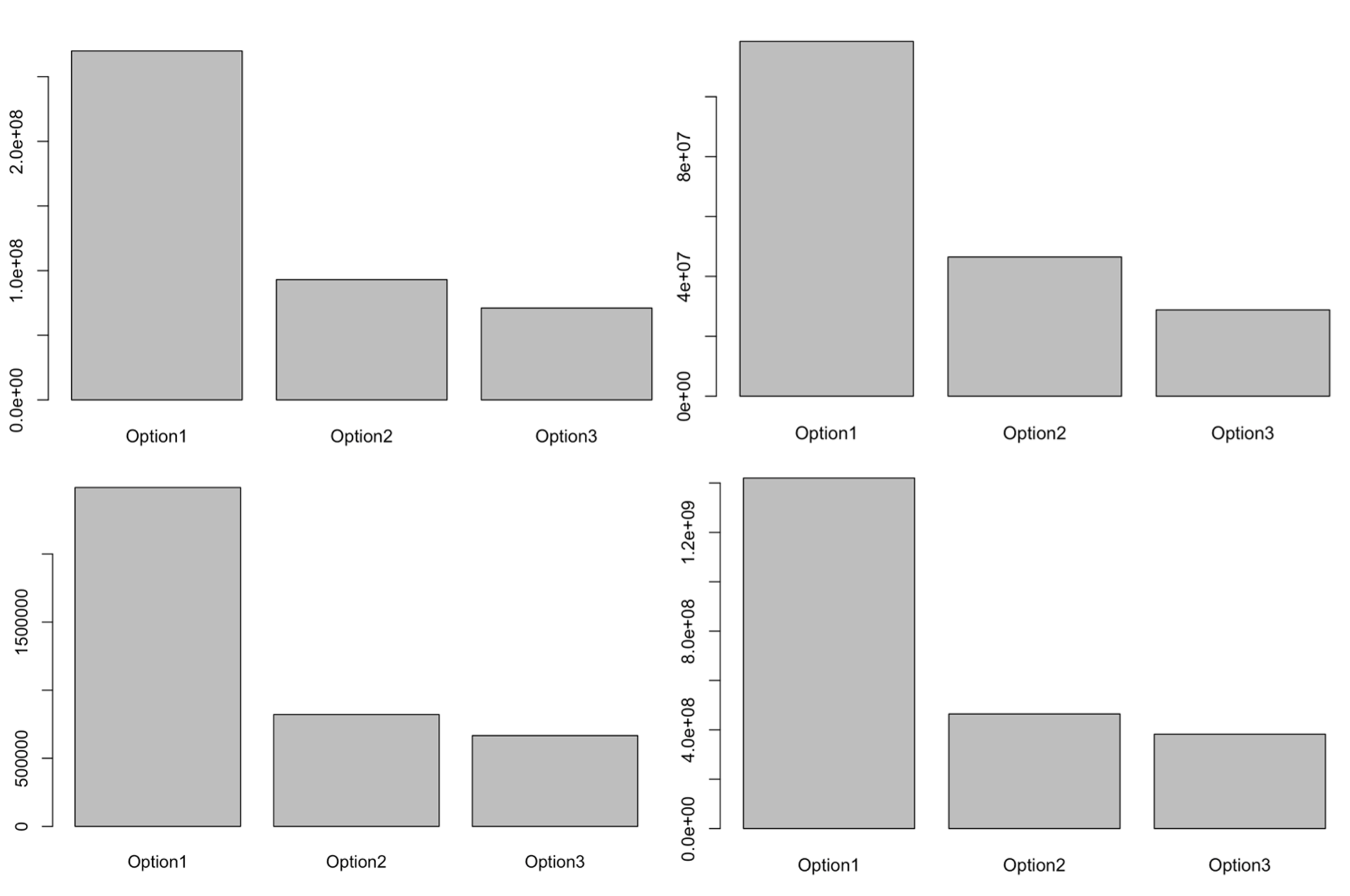
LCA Results
As shown, the four charts indicate that Option 1 has the highest energy consumption and emissions across all categories. Options 2 and 3, utilizing fiber-reinforced polymer (FRP), are more energy-efficient and generate lower CO2, NOx, and SO2 emissions. Overall, Options 2 and 3 demonstrate significantly better environmental performance than Option 1.
Another useful tool for selecting the best design option is the Multi-Criteria Decision Method, Analytic Hierarchy Process (AHP). This method allows for pairwise comparison of each design option based on the performance indicators defined in the LCA.
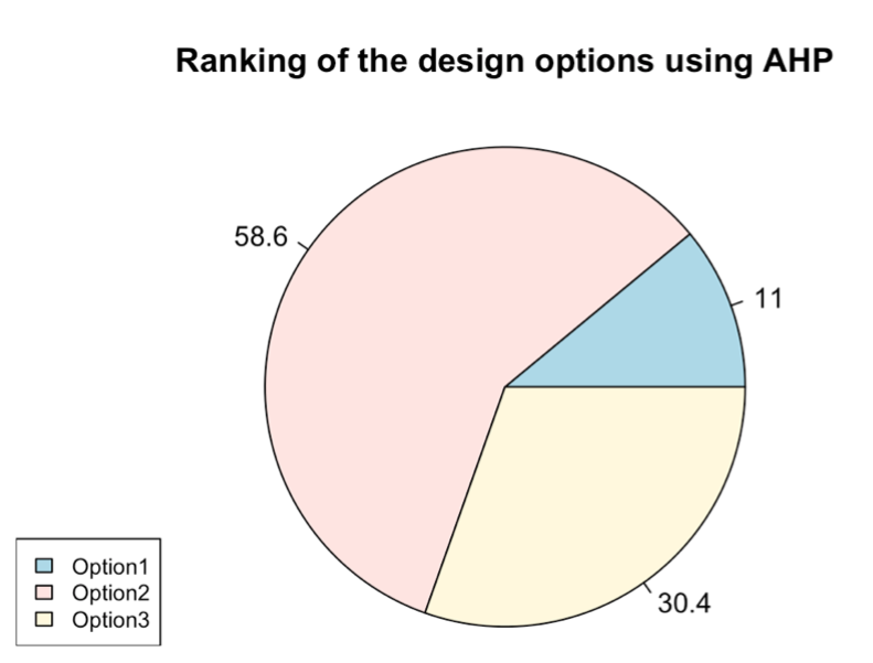
Analytical Hierarchy Process applied to the design decision
After using the AHP Method, option 2 (58.6%) is the best choice, combining cast-in-place concrete for the crest and fiber-reinforced polymer (FRP) for the guide walls, providing optimal durability, performance, and construction speed.
References:
[1] https://krcd.org/2023/06/29/news-release-pine-flat-dam-spillway-operations/
[2] Bemessung und Betrieb von Talsperren und Hochwasserrückhaltebecken, U. Maniak
[3] https://www.britannica.com/technology/spillway-engineering
[4] https://www.cement.org/cement-concrete/how-cement-is-made/
Steel Liquid Storage Tank | Water Distribution Network | Dam | Primary Sedimentation Tank/Wastewater Treatment